
Types of Insulators in Transmission Lines

0
Types of Insulators
Insulators may appear to be passive, silent components — but they carry one of the most demanding jobs in power engineering. They must simultaneously block hundreds of kilovolts of electrical stress, bear tonnes of mechanical tension, and perform flawlessly through decades of rain, pollution, lightning, and ice.

Selecting the wrong insulator type doesn't just risk equipment failure. It risks grid-wide outages, arc flash events, and fires. Understanding the full range of insulator types — and the engineering logic behind each — is essential knowledge for anyone working in transmission or distribution.

Why Insulators Are Never Simple?

The primary function is straightforward: electrically isolate live conductors from grounded tower or pole structures while providing mechanical support. But real operating conditions layer stress upon stress.

Operating Stresses

In service, a transmission insulator simultaneously faces electrical stress (operating voltage, switching surges, lightning impulse), mechanical stress (conductor weight, wind loading, ice, tension at dead-ends), and environmental degradation (UV, pollution, moisture, thermal cycling). No other component on the line carries this combination.

A poorly specified insulator can fail through flashover (surface discharge bridging the insulator), puncture (internal dielectric breakdown), or mechanical fracture — each with potentially catastrophic consequences. This is why insulator selection is an engineering decision, not a procurement convenience.

The Insulator Landscape at a Glance

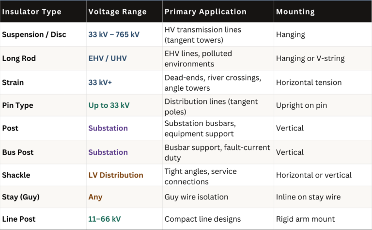
Before diving into each type, here is a complete overview of which insulator is used where, and at what voltage level:

The Insulator Landscape at a Glance

Transmission-Grade Insulators

Used above 33 kV — engineered for high electrical and mechanical demands

TYPE 01

Suspension Insulator Transmission

TYPE 02

Long Rod Insulator

TYPE 03

Strain Insulator

The workhorse of high-voltage overhead lines. Multiple disc units are linked in a chain (string) suspended from the cross-arm, with the conductor hanging from the bottom. Each disc takes a share of the total voltage — so adding or removing discs scales the string for any voltage level.

The modular construction is its key advantage: a single damaged disc can be replaced in the field without removing the full string. The naturally long creepage path along the corrugated disc surfaces also helps in polluted industrial environments.

Typical application:  33 kV to 765 kV tangent (straight-line) towers. Standard disc ratings are 70 kN or 120 kN SML (specified mechanical load).

A single-piece insulator with a solid cylindrical core and sheds along its length — no joints, no metal fittings between sheds. This seamless construction eliminates the corrosion points and puncture risks inherent in disc-type strings.

The uniform leakage path and absence of intermediate metal hardware make long rods significantly better performers under heavy contamination. Their axial compression strength means they can also serve in V-string configurations that reduce conductor galloping.

Typical application: EHV (220–765 kV) lines in coastal, industrial, and high-pollution zones where disc strings would need frequent cleaning.

Structurally, strain insulators are often disc-type units — but they are strung horizontally rather than vertically. Where suspension strings carry the weight of the conductor, strain strings carry the full tension of the conductor, which can reach hundreds of kilonewtons at river crossings or long-span sections.

At dead-end towers, the strain insulator is the last mechanical barrier between the energised conductor and the grounded tower steel. Mechanical failure here means the conductor falls.

Typical application: Angle towers, dead-ends, river crossings, and any location where the line changes direction or terminates.

Transmission-Grade Insulators

Distribution Insulators

TYPE 04

Pin Type Insulator

TYPE 05

Shackle Insulator

TYPE 06

Line Post Insulator

One of the oldest insulator designs still in production. A tapered pin screws into the pole cross-arm; the insulator mounts on top; the conductor is bound to the groove at the insulator's top with annealed wire. No suspension hardware required.

Their simplicity and low cost make them ideal for rural and semi-urban distribution lines. The limitation is voltage: as system voltage rises, the pin insulator must grow in size and weight to the point where it becomes impractical above 33 kV, at which point suspension types take over.

Typical application: 11 kV and 33 kV distribution networks, particularly on straight-line tangent poles.

Small, robust, and versatile, the shackle (or spool) insulator is a staple of low-voltage distribution. It can be mounted horizontally or vertically, making it adaptable to service connections at awkward angles that would be difficult with other types.

Common in both urban service drops and rural last-mile connections, they are particularly valued at corners and sharp bends in the line where standard suspension hardware can't easily accommodate the change of direction.

Typical application: LV service connections, distribution pole corners, and short-span rural lines.

A rigid insulator that projects horizontally from the pole or tower structure, clamping the conductor in a fixed position. Unlike suspension strings that allow the conductor to swing, line post configurations lock the conductor in place — enabling much tighter phase spacing and more compact right-of-way.

Increasingly used in urban distribution upgrades where additional circuits must be added to existing structures without widening the corridor.

Typical application: 11–66 kV compact overhead lines in urban or constrained environments.

Distribution Insulators

Substation Insulators

Engineered for rigidity, high fault-current duty, and compact switchyard layouts

TYPE 08

Bus Post Insulator

TYPE 07

Post Insulator

TYPE 09

Stay (Guy) Insulator

Where transmission insulators hang, substation post insulators stand — mounted vertically on steel frames, they support live conductors and busbars rigidly above the ground. Their design must resist not only normal load but also the severe cantilever forces from short-circuit events, where electromagnetic forces between adjacent conductors can reach multiple tonnes.

Post insulators are rated for both their cantilever strength and their electrical performance under combined lightning impulse and switching surge duty.

Typical application: All voltage levels in air-insulated substations (AIS), supporting busbars, disconnectors, and instrument transformers.

A specialised evolution of the standard post insulator, bus post insulators are optimised for busbar support duty — where multiple insulators share the continuous mechanical load of a heavy copper or aluminium busbar run, plus the dynamic forces during fault clearing.

They are typically rated to higher fault-current mechanical withstand than standard post types, and their mounting dimensions follow standardised spacing to suit common switchgear bolt patterns.

Typical application: Substation busbars at 11 kV through 400 kV, particularly where high fault-level duty is expected.

A deceptively simple but safety-critical device. Guy wires anchor poles against the tension of conductors — but if a live conductor fell and contacted the guy wire, the entire wire down to ground level would become energised, creating an electrocution hazard for anyone near the pole base.

The stay insulator is inserted inline in the guy wire at a safe working height, breaking the metallic continuity. Below the insulator, the lower portion of the guy remains at earth potential even if the upper section becomes live.

Typical application: All pole-mounted lines using guyed construction, at the regulatory-specified height above ground.

Substation Insulators

Material Deep Dive: Porcelain, Glass, and Polymer

Insulator performance is fundamentally determined by material. Modern power systems use three distinct material families, each with distinct trade-offs:

Material Deep Dive: Porcelain, Glass, and Polymer
Glass advantage: When a toughened glass disc fails internally, it shatters visibly — the lost disc is immediately apparent during aerial inspection or line patrol. A defective porcelain or polymer unit can be invisible to inspection yet at the threshold of failure. For large networks, this self-announcing failure mode significantly reduces the cost of routine surveillance.

Engineering Criteria for Insulator Selection

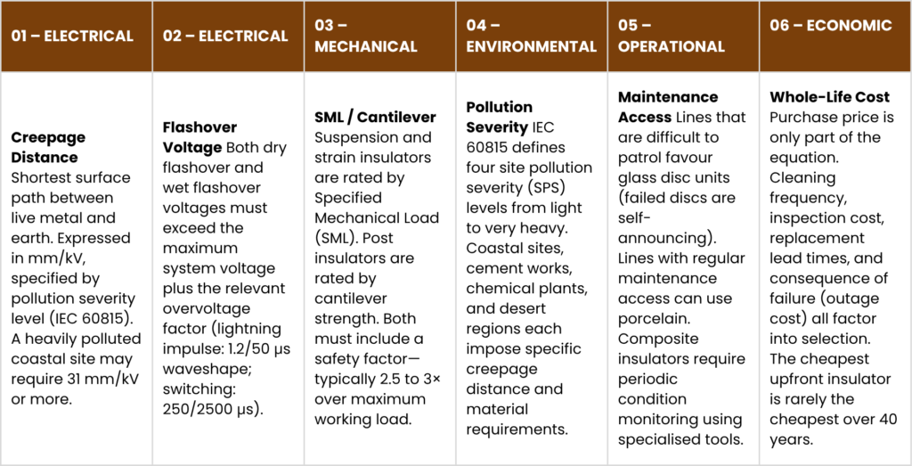
No single insulator type suits every situation. Selection is a multi-variable engineering optimisation across the following criteria:

Engineering Criteria for Insulator Selection
Creepage Distance Calculator — IEC 60815

Failure Modes and What They Tell You

Understanding how insulators fail is as important as understanding how they work. The three principal failure modes each have distinct causes and signatures:

Flashover is a surface discharge that bridges the insulator from live to earth without penetrating the material. It is usually caused by contamination combined with moisture — pollutants lower the surface resistivity, leakage current heats and dries local spots into "dry bands," and the concentrated voltage across the dry band drives a partial arc that eventually completes. Flashover is typically recoverable: the insulator survives and the line can be re-energised after the transient clears. However, repeated flashovers erode the glaze and can eventually lead to puncture.

Puncture is an internal dielectric breakdown through the body of the insulator. It is caused by manufacturing defects, overvoltage events, or accumulated degradation. A punctured disc must be replaced. In porcelain, puncture is silent and invisible from the outside — a string that has suffered puncture may appear intact while providing dangerously reduced insulation. This is why high-voltage testing of in-service strings is a routine maintenance activity.

Mechanical failure — fracture, cap-and-pin separation, or composite rod delamination — drops the conductor. It can result from manufacturing defects, fatigue under cyclic wind loading, ice storm events, or hardware corrosion releasing disc connections. Mechanical failure is the most consequential and is the primary driver of safety factor requirements in mechanical ratings.

Condition Monitoring

Modern grid operators use infrared thermography (hot spots from leakage current), UV corona cameras (partial discharge imaging), and ultrasonic detectors (acoustic corona) to detect degrading insulators before they fail. For composite insulators, dielectric loss measurement is emerging as the standard non-destructive test for tracking polymer degradation in service.

Conclusion

Every conductor in every overhead transmission or distribution line is held in place, and held safely apart from the structure beneath it, by an insulator. That insulator was selected through an engineering process that balanced voltage level, mechanical load, pollution exposure, material cost, and maintenance philosophy.

From the humble pin type insulator on a rural 11 kV line, to a long rod composite string on a 765 kV bulk power corridor, the engineering intent is identical: keep the current on the wire, and keep the people on the ground safe.

Understanding which insulator belongs where — and why — is the foundation of reliable overhead line engineering.

About the Author:

Meghna Baid

Meghna Baid is a marketing professional with 7 years of experience, specializing in the electrical industry. She excels in brand building, strategic messaging, and high-impact campaigns, blending creativity with data-driven precision. With a sharp understanding of B2B and technical markets, she crafts compelling narratives that drive results and build strong industry connections.

Reach out to her at marketing@relcoelectrical.com

Related Post:https://www.linkedin.com/feed/update/urn:li:activity:7455571262195748864


Leave a Reply

Your email address will not be published. Required fields are marked *