
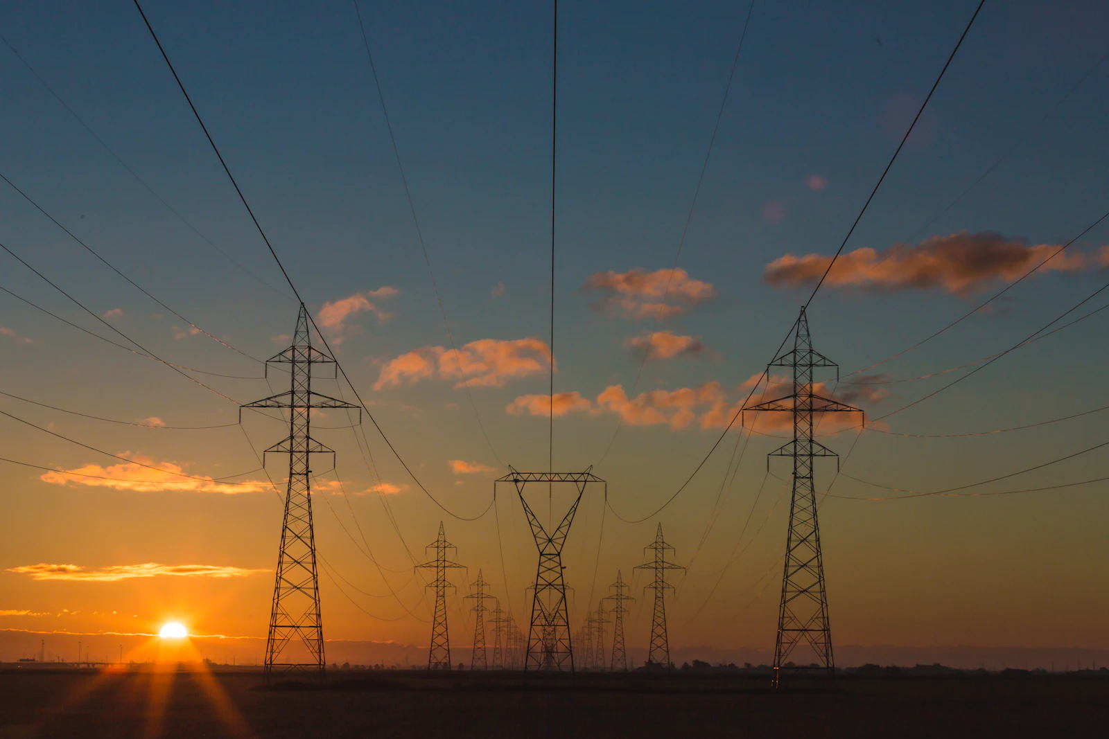
When you look up at high-voltage transmission lines stretching across the landscape, you will notice they are never pulled perfectly taut. Instead, they form a distinct, sweeping curve between the towers. This intentional dip is known as sag.
While it might look like a structural flaw or a sign of aging equipment, sag is a critical, highly engineered necessity in electrical transmission. To truly understand the mechanics of conductor sag, we must look deeper into the structural engineering, fluid dynamics, and thermodynamic principles that utility grid engineers calculate every day. Sag is not just a byproduct of gravity; it is a finely tuned variable in an equation that balances electrical capacity against catastrophic structural failure.
The Classification of Sag: Initial vs. Final
When a transmission line is constructed, engineers cannot simply measure the line's position on day one and assume it will stay there. Metal changes physically over time under constant mechanical stress, requiring engineers to design for two distinct life stages of the line:
- Initial Sag: This is the sag immediately after the conductor is strung and tensioned onto the supporting structures. The metal is brand new, and its crystalline structure has not yet been subjected to prolonged environmental stress, heavy ice accumulation, or high thermal cycles.
- Final Sag: Over months and years of operation, the conductor experiences a phenomenon known as mechanical creep. Under the continuous tensile load of its own heavy weight and the constant expansion and contraction of day-to-day power transmission, the metal molecules permanently shift and elongate. Final sag represents the maximum deflection the line will reach after this creep has fully stabilized—typically calculated over a 10-year operational horizon. Utility companies must build towers based on final sag limits to ensure the line never violates statutory ground clearances decades into the future.
Detailed Factors Influencing Conductor Sag
While gravity provides the baseline downward force, a transmission line's sag profile is dynamic. It responds continuously to a complex matrix of thermodynamics, metallurgy, geography, and fluid dynamics.
1. Thermal Expansion and Joule Heating ($I^2R$ Losses)
Transmission lines are suspended out in the open, making them highly sensitive to temperature variations. Two distinct heat sources drive the linear expansion of the metal:
- Ambient and Solar Loading: Direct sunlight (ultraviolet radiation) and high surrounding air temperatures heat the metal externally. On a calm summer day with high solar irradiance, a dark conductor can easily absorb enough heat to reach 60°C before even carrying a single ampere of current.
- Joule Heating: As electrical current ($I$) passes through a conductor, the inherent electrical resistance ($R$) of the metal converts a portion of that energy into heat, mathematically expressed as $I^2R$ losses. During periods of peak power demand, the current spikes. This internal heat generation can push conductor core temperatures past 90°C (194°F) for standard lines, and up to 200°C for specialized lines.
As the metal absorbs this dual thermal load, its atoms vibrate more violently, causing the material to expand linearly. Because the distance between the two fixed transmission towers remains identical, the newly created physical length of the wire has nowhere to go but downward, drastically increasing the sag profile and dropping the line closer to the terrain below.
Cold / Low Load Profile
• Reduced Line Length
• Maximum Ground Clearance Achieved
Hot / Peak Load Profile
• Volumetric Elongation
• Critical Clearance Reduction Range

2. Conductor Metallurgy and Composite Structural Cores
Modern high-voltage transmission grids rarely use pure copper or pure aluminum cables. Pure copper is exceptionally conductive but far too heavy and expensive for long spans, causing it to sag under its own immense weight. Pure aluminum is lightweight and a great conductor, but it lacks the tensile strength required to stretch across long distances without snapping. To solve this, utilities utilize advanced composite conductors designed to balance weight, conductivity, and tensile resistance:
- ACSR (Aluminum Conductor Steel Reinforced): This is the traditional workhorse of the global power grid. It features a high-strength central core made of galvanized steel strands, which provides the mechanical tensile strength required to resist sag. Wrapped around this steel core are multiple layers of highly conductive aluminum strands that carry the actual electrical current.
- ACSS (Aluminum Conductor Steel Supported): A highly advanced variation where the aluminum strands are fully annealed (pre-softened by heat treatment during manufacturing). Because the aluminum is already relaxed, the high-strength steel core carries virtually 100% of the mechanical tension. This allows ACSS to operate continuously at much higher temperatures (up to 200°C) without suffering from additional thermal creep or severe structural sag, making it ideal for high-capacity lines.
3. The Span Profile (Equal vs. Unequal Tower Heights)
The baseline mathematical models for power lines assume that the transmission towers sit on a perfectly flat plane, meaning the support points are at identical elevations. However, real-world transmission lines must traverse varied geography, including hills, valleys, river crossings, and mountain ranges.
- Equal Level Spans: On flat ground, the layout is perfectly symmetrical. The lowest point of the conductor—known as the vertex or the apex of the curve—occurs exactly at the horizontal midpoint between the two supporting towers. The mechanical tension is distributed equally to both structures.
- Unequal Level Spans: When a transmission line runs from a tower anchored on a steep hillside down to a tower situated in a valley, the geometry shifts completely. The lowest point of the sag migrates horizontally away from the center, moving closer to the lower tower. In rugged, mountainous terrain, the slope can be so extreme that the mathematical vertex shifts completely outside the space between the towers. This creates an intense upward vertical force on the higher tower and puts an immense downward deadweight load on the lower tower.
Planar Terrain (Equal Elevation)
Symmetrical Tension Distribution Matrix
Asymmetric Terrain (Variable Slopes)
Unbalanced Vertical Vector Forces on Anchors
4. Atmospheric Ice Loading Mechanics
In colder climates, winter weather introduces a severe, dangerous variable: freezing rain and ice accumulation. When supercooled water droplets strike a cold conductor, they instantly freeze, forming a thick, heavy radial sleeve of ice around the wire. This alters the physics of the span in two ways:
- Heavy Deadweight: Ice adds considerable deadweight. A thick coating can easily double or triple the effective weight per meter of the cable, pulling it drastically downward.
- Aerodynamic Alteration (Conductor Galloping): A clean conductor has a uniform, round cross-section that allows high winds to pass smoothly around it with minimal resistance. However, when ice builds up unevenly, it deforms the cable, creating an asymmetric shape that mimics an aerodynamic airfoil (an airplane wing). When strong crosswinds blow across an ice-coated line, this shape generates aerodynamic lift. The line begins to bounce up and down in low-frequency, high-amplitude oscillations known as conductor galloping. These violent waves can rip the conductors off their insulators, bend steel tower cross-arms, or cause different electrical phases to physically collide, triggering explosive short-circuits.
5. Wind Loading Mechanics and Line Swingout
Wind does not act as a downward force; it exerts a horizontal, lateral pressure against the surface area of the cable. The total effective weight acting on a sagging line must therefore be calculated as a vector combination. Engineers use a right-angle vector triangle where the actual weight of the conductor and the added ice weight act as the vertical vector, while the wind pressure acts as the horizontal vector. This total effective weight forces the conductor to swing outward away from the vertical plane at an angle known as the swingout angle. Because the line is pushed sideways, its sag profile is no longer hanging straight down; it is tilted along a diagonal plane.
Deriving the Mathematics: Catenary vs. Parabola
A flexible cable hanging under its own weight naturally forms a catenary curve, mathematically represented by a hyperbolic cosine function. The true formula to find the exact shape of the conductor curve is:
y = c * cosh(x/c)
However, calculating hyperbolic functions across thousands of grid spans during field installations is computationally intensive. Because the mechanical tension inside a high-voltage transmission line is intentionally kept high, and the total vertical sag is relatively small compared to the massive horizontal span length, the catenary curve can be mathematically approximated as a parabola.
• w = Total combined effective weight per unit length ($\text{kg/m}$)
• L = Span length (the horizontal distance between supporting towers)
• T = Conductor tension ($\text{Newtons}$)
From this formula, we can extract critical engineering insights:
- Span Dependency: Sag does not scale linearly with distance; it scales exponentially based on the square of the span length ($L^2$). If an engineering team decides to double the distance between two transmission towers ($2L$), the vertical sag does not double—it increases by a factor of four ($4S$).
- Tension Dependency: Sag is inversely proportional to the horizontal tension. If a utility company attempts to eliminate half of the sag by cranking the wire tighter, the tension inside the line exactly doubles. This dramatically amplifies the mechanical pull on the dead-end towers, requiring thicker steel reinforcements and massive concrete foundations to keep the towers from collapsing inward.
Exponentially drives sag depth based on the square of horizontal distance ($L^2$).
Counteracts gravity. Higher tension flattens the curve but amplifies structural load on cross-arms.
Combined downward force including composite material mass, radial ice, and dynamic wind loads.
Real-World Implications & Solutions
The Threat of a Ground Fault Blackout
On hot summer afternoons, consumer and industrial power demands peak simultaneously. As lines carry maximum current, internal joule heating combines with ambient solar heat, causing severe thermal expansion. If a utility company overloads a line, the conductor will sag below its legal safety margin. If the line hangs too close to unmaintained vegetation or trees beneath the span, the high-voltage electricity will jump across the air gap—a phenomenon known as a flashover. The electricity drains straight into the earth, creating a massive short-circuit that trips automated circuit breakers and can trigger cascading grid failures and widespread regional blackouts.
The Dynamic Line Rating (DLR) Solution
Historically, utilities calculated sag using static assumptions (e.g., assuming a worst-case hot day with zero wind) and strictly limited power capacity. Today, advanced grids use Dynamic Line Rating (DLR) to optimize the system:
- Sensors on the Lines: Utilities install real-time monitors directly onto live transmission lines to measure exact conductor temperature, physical tilt angles, or use LiDAR to track ground clearance dynamically.
- Convective Cooling: If a line carries high current but a strong breeze passes across it, the wind carries the heat away. The line stays cool, preventing thermal expansion and keeping sag minimal.
- Real-time Adjustments: DLR software allows grid operators to safely pump up to 30% to 40% more electricity through the exact same wires during windy or cooler hours, maximizing grid efficiency without risking a ground fault.