
In electrical safety, grounding protects lives, equipment, and infrastructure by providing a safe path for fault and lightning currents. Galvanized Iron (GI) strips and plates dominate grounding systems worldwide, especially in challenging environments like India’s varied soils. Their blend of durability, conductivity, and affordability makes them indispensable.
This guide explores the engineering, standards, and applications that position GI as the top choice for reliable electrical grounding.
Core Advantages: Why Choose GI for Grounding?
GI excels in earthing and lightning protection due to these key properties:
- Superior Corrosion Resistance: Hot-dip zinc coating acts as a sacrificial barrier, shielding steel from rust and extending life in aggressive soils.
- Excellent Conductivity: Steel handles fault and lightning currents effectively when sized per IS 3043 and IEEE 80, though less conductive than copper.
- High Tensile Strength: Withstands installation stresses and soil shifts, maintaining network integrity.
- Cost-Effectiveness: Far cheaper than copper for large-scale projects like substations, without sacrificing safety.
- Versatility in Soils: Thrives in high-resistivity or rocky terrains common in India.
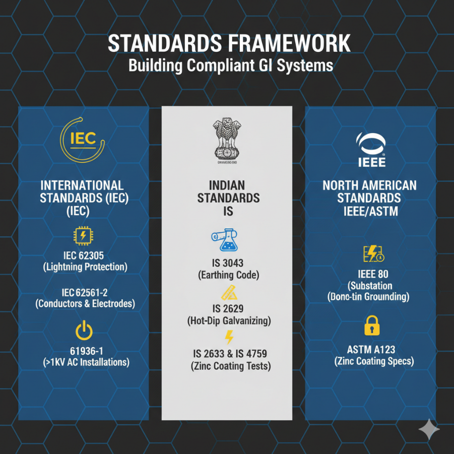
Standards Framework: Building Compliant GI Systems
Safe designs follow global and local codes. Here’s the roadmap.
International Standards (IEC)
- IEC 62305: Governs Lightning Protection Systems (LPS), integrating GI strips for lightning dissipation.
- IEC 62561-2: Specifies conductors and electrodes, including GI strip dimensions and tests.
- IEC 61936-1: Guides >1 kV AC installations, mandating GI grids for substation safety.
Indian Standards (IS)
- IS 3043 (Earthing Code): Core reference; mandates 6 mm minimum GI plate thickness and strips like 25×3 mm or 50×6 mm based on fault levels.
- IS 2629: Hot-dip galvanizing practices.
- IS 2633 & IS 4759: Zinc coating uniformity and testing.
British/European (BS EN)
- BS 7430: Earthing calculations for GI electrodes.
- BS EN 62561: Lightning protection components.
North American (ASTM/IEEE)
- IEEE 80: Substation grounding guide; calculates step/touch voltages and GI sizing.
- ASTM A123: Zinc coating specs.
Key Specifications & Design Parameters
Design GI systems around fault current, soil resistivity, and codes. Use this table for quick reference:
| Component | Standard Dimensions | Minimum Thickness | Key Standard |
| GI Plates | 600 mm x 600 mm | 6 mm (buried) | IS 3043 |
| GI Strips (Substation) | 25×3 mm, 32×6 mm, 40×6 mm, 50×6 mm | 3-6 mm | IEEE 80, IS 3043 |
IEEE 80 Formula Insight: Minimum cross-section Ag = ( If √t ) / K, where If is fault current, t is clearing time, and K factors material properties (steel/zinc fusion temp). This prevents melting under max faults.
Practical Applications
GI grounding shines in these scenarios:
- Substations: Buried meshes create equipotential zones (IEC 61936-1, IEEE 80).
- Lightning Protection: Down-conductors and electrode rings (IEC 62305).
- Industrial Plants: Grounds machines and structures against faults/static.
- Telecom Towers: Low-impedance lightning paths.
- Buildings: Main electrodes for metal frameworks.
Installation Best Practices & Corrosion Management
- Select GI per IS 2629/ASTM A123 for thick, uniform zinc (80-100 μm min).
- Weld connections exothermically or use compression lugs for corrosion-proof bonds.
- Backfill with bentonite in corrosive soils to cut resistivity.
- Test resistance annually via fall-of-potential method; inspect joints.
GI vs. Copper: A Comparative Breakdown
While the text mentions cost, a direct comparison table helps procurement managers justify the choice of GI.
| Feature | Galvanized Iron (GI) | Copper (Cu) |
| Conductivity | Moderate (Suitable for high-current faults) | High |
| Cost | Economical (approx. 3x cheaper) | Expensive |
| Durability | High (Zinc protects against soil corrosion) | High (But prone to theft) |
| Best Use Case | Substations, Industrial Plants, Railways | Sensitive Electronics, Telecom |
Common Mistakes to Avoid in GI Plate Earthing Setup
Setting up GI plate earthing demands precision to ensure safety and longevity. Skipping these pitfalls prevents failures in fault dissipation and corrosion resistance.
- Oversights in Site Preparation
Inadequate soil testing leads to poor electrode performance. Always measure soil resistivity first—high values (>100 Ω-m) require deeper burial or chemical treatment like bentonite, as per IS 3043. Burying the 600x600x6 mm GI plate too shallow (<2-3 m) exposes it to dry surface conditions, spiking resistance.
- Material & Connection Errors
Using under-galvanized plates (<80 μm zinc per IS 4759) accelerates corrosion in acidic or saline soils. Loose mechanical clamps instead of exothermic welds create high-resistance joints that overheat during faults, violating IEEE 80 tolerances.
- Installation & Maintenance Flubs
Neglecting a 50-100 mm sand-cum-salt-charcoal backfill layer around the plate hampers moisture retention and conductivity. Forgetting annual fall-of-potential resistance tests (>1-5 Ω thresholds per site) misses degradation early, risking step/touch voltage hazards.
| Mistake | Consequence | Fix |
| No soil resistivity test | High earth resistance | Test & treat soil [IS 3043] |
| Thin galvanizing | Rapid zinc depletion | Verify 80-100 μm coating |
| Shallow burial | Surface drying | Minimum 3 m depth |
| Poor connections | Fault overheating | Exothermic welding only |
| No backfill | Low conductivity | Sand-salt-charcoal layer |
Relco Electricals Case Studies: GI Grounding Success Stories
Relco Electricals, with 30+ years in electrical safety solutions, has deployed GI strips and plates in high-stakes Indian projects, ensuring compliance with IS 3043 and IEEE 80. These anonymized examples highlight real-world performance in substations, railways, and industries.relcoelectricalsindia+2
Case Study 1: 132 kV Substation Grid, Northern India
Relco supplied 50×6 mm GI strips for a full underground mesh grid in a 132 kV substation amid rocky, high-resistivity soil (500 Ω-m). The design per IEEE 80 limited step/touch voltages to safe levels (<500 V), handling 40 kA fault currents. Post-install, earth resistance dropped to <1 Ω; no corrosion after 3 years, cutting maintenance by 40%.imimg+1
Case Study 2: Railway Traction Earthing, 25 kV OHE
For Indian Railways’ overhead equipment (OHE), Relco integrated 40×6 mm GI strips with FRP discharge rods for 25 kV AC lines. Exothermic welds ensured permanent bonds; system dissipated induced surges during monsoons, preventing flashovers. Resistance stayed <5 Ω over 2 years in corrosive coastal soil, enhancing crew safety.relcoelectrical+1
Case Study 3: Industrial Plant Expansion, Renewables Hub
In a solar-wind hybrid plant, Relco used 600x600x6 mm GI plates and 32×6 mm strips for 200+ equipment grounds. Bentonite backfill addressed acidic soil; IEEE 80 calcs confirmed equipotential zoning. Fault simulation tests verified zero outages, with 15-year projected life—economical vs. copper at 60% lower cost.relcoelectrical+1
6. Relco Case Studies: Proven GI Deployments
Relco Electricals delivers turnkey GI grounding, as shown below.relcoelectricalsindia
| Project | GI Specs | Key Outcome | Standards |
| 132 kV Substation | 50×6 mm strips, mesh grid | <1 Ω resistance, 40% less maintenance | IEEE 80, IS 3043 relcoelectricalsindia+1 |
| 25 kV Railway OHE | 40×6 mm strips + rods | Surge protection in monsoons | IEC 62305 relcoelectrical+1 |
| Renewables Plant | 6 mm plates + 32×6 mm strips | Zero faults, 60% cost savings | IS 3043 relcoelectrical+1 |
Maintenance Checklist (The “Aftercare”)
Adding a “Value-Add” section for maintenance increases the page’s utility and “shareability.”
- Quarterly Visual Inspection: Check for loose connections or mechanical damage at the test link.
- Watering the Pit: In peak summer, ensure the earthing pit is watered to maintain moisture levels.
- Resistance Logging: Document annual resistance values. If resistance increases by >20%, investigate soil condition or zinc depletion.
Conclusion
GI strips and plates deliver proven, standards-backed grounding—at Relco Electricals, we’ve seen them safeguard infrastructure for decades. Adhere to IS 3043, IEEE 80, and IEC for optimal results. Consult qualified engineers for site-specific designs.
FAQ
Q: Why is 6 mm the standard thickness for GI plates?
A: Per IS 3043, 6 mm ensures that even with natural corrosion over 15–20 years, the plate maintains enough structural integrity and cross-sectional area to dissipate fault currents safely.
Q: Can we use GI and Copper together?
A: It is discouraged due to Galvanic Corrosion. When two dissimilar metals touch in the presence of an electrolyte (moisture), the GI will corrode rapidly. Always use bimetallic connectors if a transition is necessary.
Q: How does hot-dip galvanizing differ from cold galvanizing?
A: Hot-dip (per IS 2629) creates a metallurgical bond and a thicker coating (80–100 μm), whereas cold galvanizing is essentially zinc-rich paint and will not survive underground.
Reference
- https://www.relcoelectricalsindia.in
- https://www.relcoelectrical.com/insulated-hand-tools.html
- https://www.relcoelectrical.com
- https://5.imimg.com/data5/SELLER/Doc/2025/6/519644703/DY/JS/CW/42918306/stay-rod-set.pdf
- https://relcoelectricals.com/product/earth-discharge-rod-for-railway/
- https://www.indiamart.com/proddetail/galvanized-iron-strips-2854301805097.html
- https://www.indiamart.com/proddetail/relco-telescopic-earth-discharge-rod-2854649518948.html
- https://www.indiamart.com/proddetail/earth-discharge-rod-for-railway-2856723141912.html
- https://in.linkedin.com/company/relcoelectricals
- https://relcoelectricals.com