

The Grid is Healthy. So Why Does the Relay See Low Voltage?
Uncovering hidden measurement circuit failures, secondary wiring faults, and why advanced VT supervision logic is vital for modern substations.
In high-voltage electrical transmission and distribution networks, system reliability is paramount. However, power system engineers and substation operators frequently encounter a perplexing diagnostic scenario: The main high-voltage transmission grid is completely healthy, line currents are balanced, and system frequency is stable, yet the protection relay suddenly flags a severe low-voltage condition or triggers an unwanted trip.
When this happens, initial panic often points toward major grid-level instabilities, phase-to-ground faults, or sudden load rejections. But more often than not, a deep-dive investigation reveals that the primary power lines are completely fine. Instead, the root cause is stealthily hiding right inside the measurement and secondary circuit infrastructure.
In this comprehensive technical guide, we will analyze why this dangerous discrepancy occurs between the actual system voltage and the signal captured by the relay, how it threatens critical protective functions, and how modern numerical relays utilize advanced supervision logic to prevent costly false outages.
The Core Discrepancy: Actual System Voltage vs. Relay Perspective
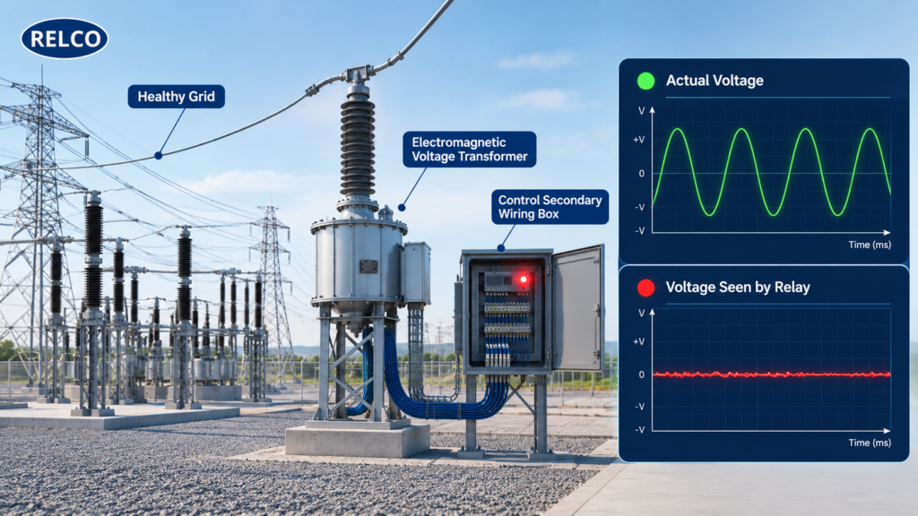
Under normal operating parameters, the primary high-voltage busbar generates a clean, continuous, and stable sinusoidal waveform. High-voltage instrument transformers (Voltage Transformers or Potential Transformers) step down this massive voltage to safe, manageable secondary levels (typically 110V or 63.5V) for numerical relays to process.
However, the analog signal that ultimately arrives at the protection relay’s terminal block can look drastically different from what is happening on the primary side. Several factors distort this journey:
- Secondary Wiring Degradation: High-resistance joints, oxidized terminal blocks, or loose screw connections in the control room marshalling box create localized voltage drops.
- Electromagnetic Unit Discrepancies: Internal winding degradation, core saturation, or ratio imbalances within the electromagnetic measurement components lead to erratic signal transfer.
- Blown Fuses and MCB Trips: Miniature Circuit Breakers (MCBs) or secondary protection fuses blowing on a single phase will instantly cause the relay to see zero or heavily depressed voltage on that specific phase.
How Low-Voltage Errors Cripple Protection Functions
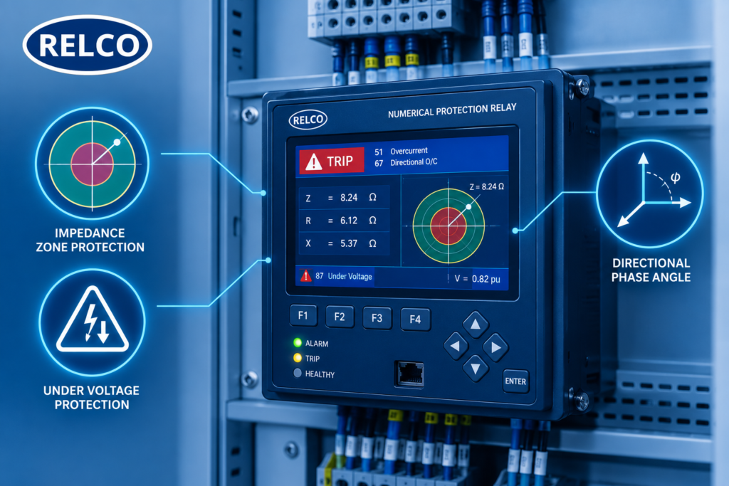
Modern protection relays are not just simple monitoring devices; they host complex mathematical algorithms that rely heavily on accurate voltage inputs to execute mission-critical protection functions. When a measurement error falsifies the voltage reading, multiple functions misbehave:
Function 21: Distance Protection
Distance relays continuously calculate apparent impedance using Ohm’s law. If a secondary wiring error causes voltage to plummet while line current remains completely normal, the relay calculates an artificially low impedance value. This tricks the relay into believing a fault has occurred right inside its zone, resulting in a dangerous false trip.
Functions 27/59: Under/Over-Voltage Protection
These elements are dedicated to monitoring grid voltage thresholds. If the measurement path drops voltage below the set threshold, the relay assumes a system-wide brownout or collapse and isolates the feeder unnecessarily, disrupting industrial and commercial supply.
Directional Elements
Directional overcurrent and earth-fault protections require a stable reference voltage phasor to determine whether a fault lies upstream or downstream. Distorted or collapsed voltage signals compromise phase angle relationships, leading to directional blindness.
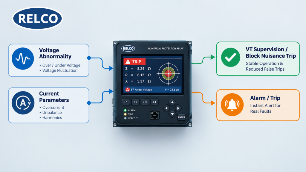
The Intelligent Solution: VT Supervision Logic (60VT)
To eliminate catastrophic nuisance tripping caused by secondary failures, modern numerical protection relays feature sophisticated built-in supervision logic, universally designated as VT Supervision (such as the 60VT function).
Instead of acting blindly on a sudden voltage drop, the relay’s internal logic cross-examines multiple system parameters simultaneously:
- Parameter Correlation: It checks whether the sudden voltage dip is accompanied by a corresponding surge in fault current or changes in negative/zero-sequence components.
- Distinction Mechanism: If voltage drops drastically but current remains completely steady and balanced, the relay deduces that the grid is healthy and the fault resides strictly within the secondary measurement loop.
- Actionable Response: The 60VT logic instantly Blocks distance and under-voltage tripping functions from operating falsely, while simultaneously raising a distinct alarm for the control room staff to investigate secondary wiring.
Engineering Best Practices for Substation Maintenance
Mitigating secondary circuit vulnerabilities requires a proactive maintenance and testing strategy. Substation engineers should adopt these standard protocols:
- Routine Loop Calibration: Conduct periodic burden testing and terminal resistance checks on all VT secondary wiring paths from the switchyard marshalling box to the control relay panel.
- MCB & Fuse Audits: Ensure auxiliary miniature circuit breakers protecting VT secondary lines are equipped with auxiliary contact monitoring linked directly to the Annunciator or SCADA system.
- Disturbance Recorder Analysis: Following any unexpected relay event, engineers must thoroughly analyze the internal event logs and COMTRADE waveform files to verify whether the trigger originated from primary network faults or secondary circuit anomalies.
Conclusion
A low-voltage indication on a protection relay is not an absolute confirmation of primary grid failure. Before initiating high-priority grid shutdowns or disrupting power delivery, maintenance teams must look closer at the measurement architecture. By understanding secondary circuit vulnerabilities and properly configuring advanced features like VT Supervision (60VT), utilities can achieve maximum network uptime, eliminate costly false trips, and preserve total power system reliability.
About the Author:
Meghna Baid is a marketing professional with 7 years of experience, specializing in the electrical industry. She excels in brand building, strategic messaging, and high-impact campaigns, blending creativity with data-driven precision. With a sharp understanding of B2B and technical markets, she crafts compelling narratives that drive results and build strong industry connections.
Reach out to her at marketing@relcoelectrical.com