
Understanding High-Voltage Disconnector Switches: Types, Functions, and Maintenance Best Practices

0
High-Voltage Disconnector Switches guide banner showing structural types and maintenance best practices by Relco Electricals

Understanding High-Voltage Disconnector Switches: Types, Functions, and Maintenance Best Practices

In modern high-voltage power transmission and distribution networks, grid reliability, operational continuity, and human safety depend entirely on the precision coordination of switching equipment. While circuit breakers perform the heavy-duty task of interrupting massive fault currents under emergency scenarios, another class of devices quietly anchors the physical safety architecture of outdoor switchyards: the high-voltage disconnector switch, commonly referred to as an isolator.

For substation design engineers, utility project heads, and electrical procurement specialists, a comprehensive technical understanding of disconnector mechanics, structural classification, compliance parameters, and lifecycle maintenance is critical. This engineering guide explores the core technical attributes that dictate disconnector performance in transmission grids.

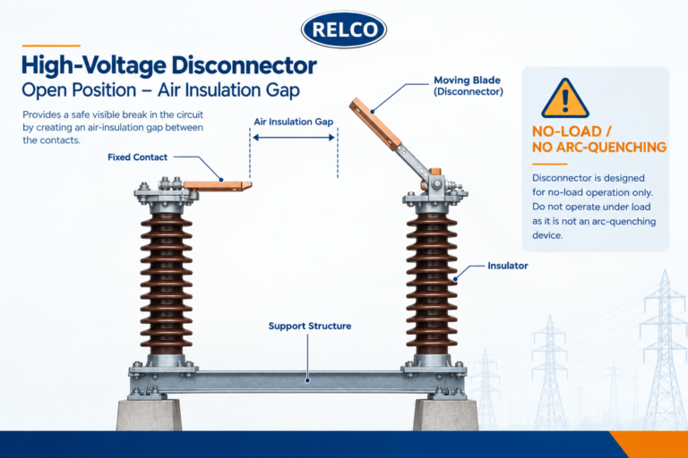
Technical cross-section diagram showing a high-voltage disconnector blade in an open position

Technical cross-section view illustrating the visible open-air insulation gap and reinforcing the critical ‘off-load / no-load’ switching safety rule.

What is a High-Voltage Disconnector Switch?

A high-voltage disconnector switch is a mechanical switching device that provides an open-circuit gap in the closed position that satisfies specific, mandated insulation requirements. Its principal operational intent is not to break load or fault currents, but rather to visibly and physically isolate a downstream section of a transmission line, transformer bay, or busbar from live voltage sources.

This physical isolation provides absolute safety assurance for maintenance and repair crews working downstream. When open, the visible air gap reassures operators that equipment is completely de-energized, mitigating any risk of induced voltages or accidental back-feeding.

The Golden Rule of Operation: No-Load Switching Dynamics

Unlike sulfur hexafluoride (SF6) or vacuum circuit breakers, standard disconnector switches possess no arc-quenching media or chambers. Consequently, they are strictly classified as off-load (no-load) switching devices.

  • The Hazard of Arcing: Opening a disconnector while current is actively flowing ionizes the surrounding air, creating an uncontrolled, high-energy electric arc. Because atmospheric air cannot rapidly quench high current, this arc can escalate into a phase-to-phase or phase-to-ground short circuit, destroying hardware and causing catastrophic arc-flash injuries.
  • Interlocking Mandates: To eliminate human error, reliable substations deploy rigorous mechanical and electrical interlock systems. These mechanisms physically prevent the operation of disconnector blades unless associated circuit breakers are confirmed to be fully open and grounded.
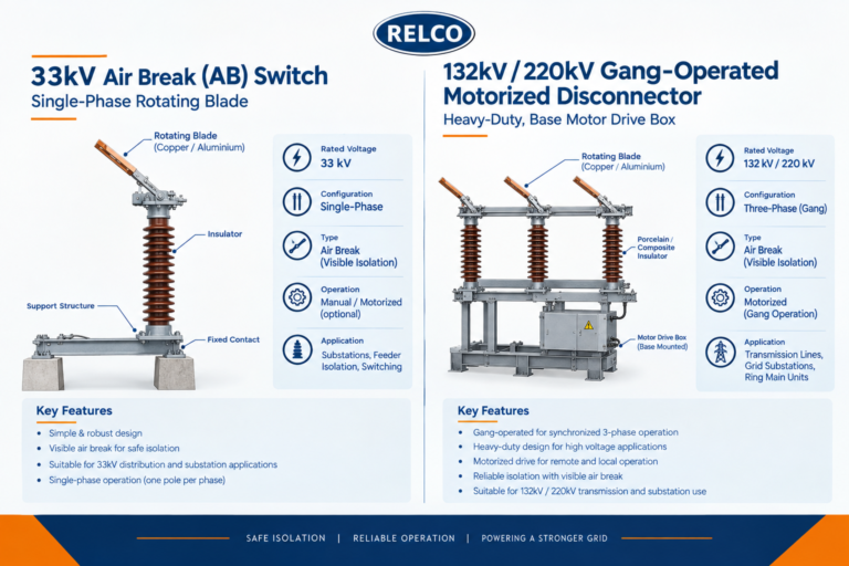
Structural and mechanism comparison between a 33kV Air Break (AB) switch (left) and a heavy-duty 132kV/220kV Gang-Operated Motorized Disconnector (right).

Structural and mechanism comparison between a 33kV Air Break (AB) switch (left) and a heavy-duty 132kV/220kV Gang-Operated Motorized Disconnector (right).

Core Architectural Types: AB Switches vs. Gang-Operated Disconnectors

Disconnector switches are engineered in various physical configurations depending on the voltage class, layout constraints of the switchyard, and system automation levels.

1. Air Break (AB) Switches

Primary Deployment: Widely utilized in rural distribution feeders, sub-transmission networks, and lower-voltage outdoor yards (typically up to 33kV).

Operational Mechanism: AB switches feature single-phase or multi-phase rotating blades that separate from fixed contacts, relying entirely on atmospheric air columns to stretch and extinguish minor charging or magnetizing currents.

Engineering Pros & Cons: Highly cost-effective and structurally simple for decentralized networks. However, they require manual operation via insulated operating rods and regular manual alignment verification.

2. Gang-Operated Motorized & Manual Disconnectors

Primary Deployment: Indispensable for high-voltage (HV) and extra-high-voltage (EHV) transmission substations operating at 132kV, 220kV, 400kV, and above.

Operational Mechanism: In a gang-operated configuration, all three phase blades are coupled mechanically to a shared operating pipe and rotating shaft. They are driven simultaneously either via a robust manual hand-crank mechanism or high-torque electric motor actuators.

Engineering Pros & Cons: Guarantees instantaneous, simultaneous phase operation, eradicating single-phasing vulnerabilities. Fully compatible with SCADA and remote substation automation systems.

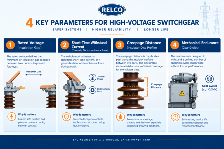
Key electrical parameter breakdown for engineering procurement under IEC standards, covering rated voltage, short-time current, and creepage distance.

Key electrical parameter breakdown for engineering procurement under IEC standards, covering rated voltage, short-time current, and creepage distance.

Critical Technical Parameters for Procurement & Design

When selecting disconnector switches for major infrastructure projects, engineering procurement teams must evaluate rigorous specifications defined under international standards such as **IEC 62271-102** and relevant national benchmarks:

Parameter Specification Technical Significance Engineering Standard Consideration
Rated Voltage (Ur) Defines the maximum system voltage the insulation system must withstand continuously. Must match grid nominal voltage levels (e.g., 33kV, 132kV, 400kV).
Short-Time Withstand Current (Ik) The capacity of closed contacts to endure electrodynamic and thermal forces during short circuits. Typically rated for 1 to 3 seconds without contact welding or mechanical distortion.
Creepage Distance Total surface distance along the insulator profile between live metal and earth. Scaled according to site pollution severity levels (Light to Very Heavy/Coastal).
Mechanical Endurance Class Quantifies the number of open-close cycles the switch can execute without failure. High-class units tested for thousands of heavy-duty mechanical cycles.
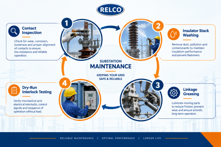
Four-step preventive maintenance checklist covering contact inspection, insulator washing, linkage greasing, and dry-run interlock testing for maximum grid uptime.

Four-step preventive maintenance checklist covering contact inspection, insulator washing, linkage greasing, and dry-run interlock testing for maximum grid uptime.

Preventive Maintenance Protocols for Maximum Grid Uptime

Outdoor high-voltage switchyards expose mechanical disconnectors to severe environmental stressors—including extreme thermal fluctuations, heavy rainfall, high humidity, wind-borne dust, and corrosive industrial or coastal pollutants. Neglecting routine maintenance can lead to high contact resistance, thermal runaway, and unexpected grid trips.

  1. Contact Surface Inspection & Pressure Verification: Over long operating cycles, copper or silver-plated contact fingers experience wear, pitting, and oxidation. Technicians must inspect contact pressure using gauges and clean contact pads with approved non-residue solvents to keep contact resistance minimal.
  2. Insulator Stack Integrity & Flashover Prevention: Porcelain or composite insulator columns accumulate conductive grime, industrial soot, and salt layers over time. Routine washing cycles—especially prior to heavy monsoon or dry-summer pollution peaks—combined with thermographic infrared scanning, help identify and eliminate micro-leakage paths.
  3. Mechanical Linkage Lubrication & Rust Mitigation: Operating rods, pivot bearings, universal joints, and gearboxes are prone to binding or seizing if exposed to moisture without adequate protection. Apply specialized, low-temperature, weather-resistant synthetic greases to all moving components.
  4. Dry-Run Functional & Interlock Testing: During scheduled system outages, maintenance teams should conduct controlled manual or motorized dry runs. This ensures that auxiliary switches, mechanical key interlocks, and electrical limit switches synchronize smoothly without lag or phase skew.

Conclusion: Securing the Future of Power Transmission Reliability

High-voltage disconnector switches are far more than simple mechanical links in an outdoor switchyard; they serve as foundational pillars of human safety, precise grid segmentation, and overall operational continuity. As modern transmission networks experience exponential shifts toward smart grid integration, automation, and higher power densities, the role of reliable, precision-manufactured isolators becomes even more critical. Compromising on switchgear quality or neglecting rigorous maintenance routines can lead to catastrophic equipment failures, costly grid downtime, and severe safety hazards.

By investing in high-grade, standard-compliant disconnector switches and adhering to proactive preventive maintenance protocols, power utilities, industrial plants, and engineering contractors can safeguard their infrastructure against environmental and electrical stresses. Choosing robust, engineered-to-last hardware ensures long-term asset performance, optimizes the total cost of ownership, and guarantees uninterrupted power delivery across complex transmission and distribution networks.

Ready to Fortify Your Power Transmission Infrastructure?

Discover Relco Electricals’ comprehensive portfolio of high-voltage disconnectors, isolators, and custom substation infrastructure engineered for uncompromising grid reliability.

Explore Our Product Catalog

About the Author:

Meghna Baid

Meghna Baid is a marketing professional with 7 years of experience, specializing in the electrical industry. She excels in brand building, strategic messaging, and high-impact campaigns, blending creativity with data-driven precision. With a sharp understanding of B2B and technical markets, she crafts compelling narratives that drive results and build strong industry connections.

Reach out to her at marketing@relcoelectrical.com

Leave a Reply

Your email address will not be published. Required fields are marked *