
Related posts
Not All Transmission Towers Are Built the Same
https://relcoelectricals.com/
Not All Power Lines Behave the Same
Power Systems Engineering • Transmission Lines • 8 min read
Electricity powers every part of modern life — from hospitals and data c...
Types of Insulators in Transmission Lines
Insulators may appear to be passive, silent components — but they carry one of the most demanding jobs in power engineering. They must ...
Why 11kV? The Hidden Engineering Behind Voltage Standards
Wherever electricity flows — from a rooftop solar array to a city of millions — voltage levels like 11kV, 33kV, 66kV, and 132kV appear ...
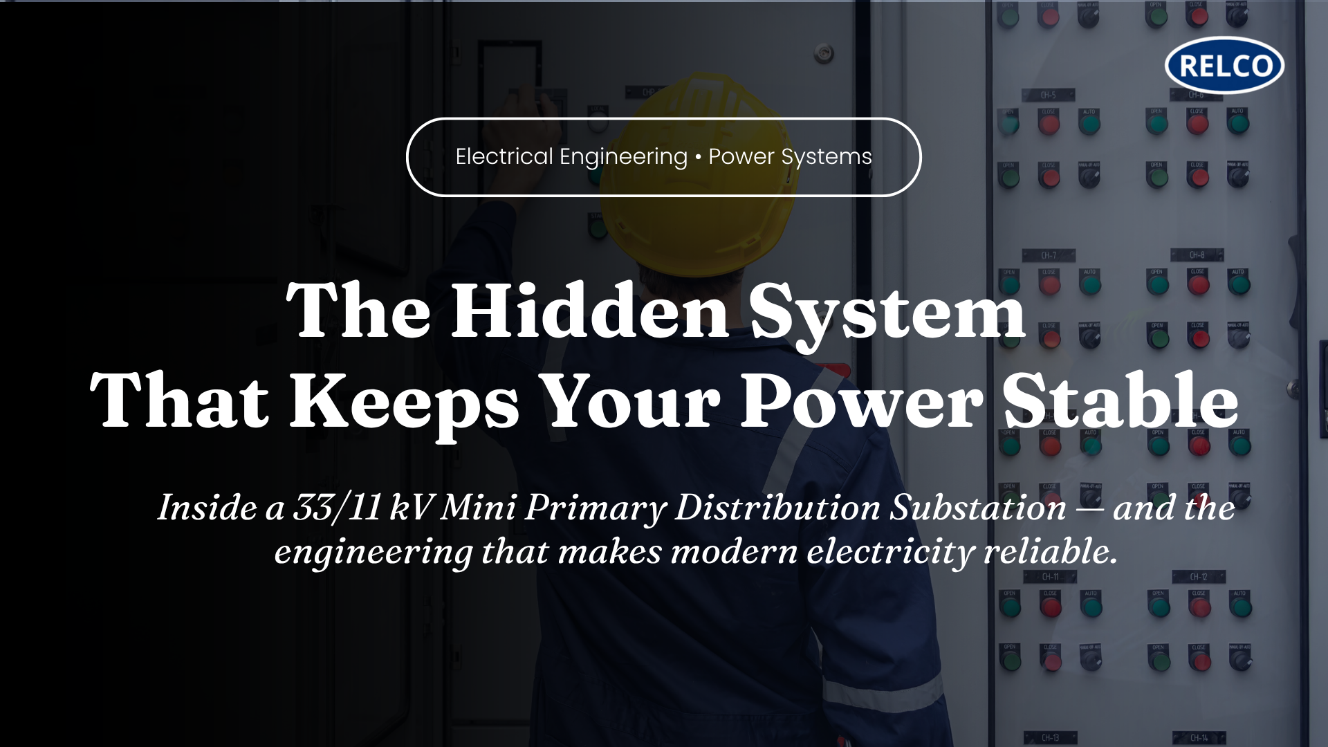
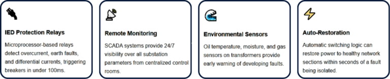
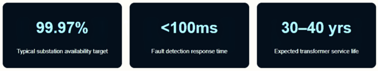
The Hidden System That Keeps Your Power Stable
Electricity is often taken for granted. A switch is flipped, and power is instantly available. But behind this seamless experience lies...
Why 3-Phase Systems Are Preferred Over Single-Phase in Electrical Engineering?
1. Introduction
Single-phase power is the standard supply for residential environments — powering lighting, fans, air conditioners, ...
Zero Accidents Is Possible: For Lineworkers on HT Lines
Introduction
Key Statistics on Lineworker Safety:
Fatal electrical injuries decreased from 2.7 per 100,000 workers in 2013 to 1.6...
Why “OFF” Is Not Enough! The Essential Role of Earthing Discharge Rods in Electrical Safety
In the high-voltage industry, the phrase "de-energized" can be deceptively simple. While turning off a breaker is the first step in any...
Choosing GI for Grounding: When It Works—and When It Doesn’t
In electrical safety, grounding protects lives, equipment, and infrastructure by providing a safe path for fault and lightning currents...