

In modern industrial infrastructure, power distribution networks, and commercial complexes, safety and stability are non-negotiable. At the foundation of every robust power architecture lies a meticulously engineered electrical earthing (grounding) system. For electrical, project, and site engineers, understanding how to design, compute, calculate, and upkeep an earth grid is critical for preventing catastrophic system failures, mitigating transient surge damage, and safeguarding human life from lethal electric shocks.
This exhaustive, end-to-end technical guide covers everything from core theoretical frameworks and international regulatory standards to advanced soil testing methods and field execution strategies.
1. Fundamental Objectives & Physics of Earthing
Earthing is much more than driving a metal rod into the ground and connecting a copper wire. It is an intentional, low-impedance electrical connection established between the metallic parts of an installation and the general mass of the earth.
Core Functions of a Robust Earthing Network:
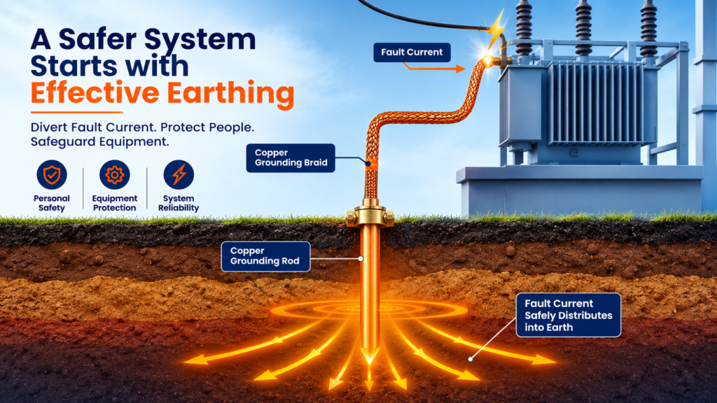
- Fault Current Dissipation: During a line-to-earth fault, massive fault currents must find an immediate, low-resistance return path to the power source. This rapid surge triggers protective devices (such as MCBs, MCCBs, or numerical relays) to isolate the circuit instantaneously.
- Overvoltage Suppression & Lightning Protection: Direct or indirect lightning strikes, switching surges, and resonance phenomena inject high-frequency, high-voltage transients into the grid. A reliable earth grid safely diverts these transient charges into the earth mass.
- Equipotential Platform Creation: By maintaining all exposed conductive surfaces (enclosures, cable racks, machine frames) at a near-zero reference potential, the system prevents dangerous potential differences across a room.
- Step and Touch Potential Minimization: Managing the voltage gradient across the earth's surface during a ground fault is critical to ensuring that personnel standing near a substation are not subjected to fatal ventricular fibrillation.
2. Deep Dive Into International Earthing Standards
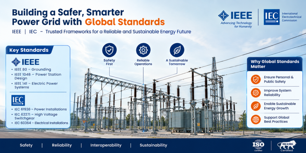
Designing an earthing installation requires strict adherence to globally accepted benchmarks. Different standards address various dimensions of safety, grid configuration, and fault handling capability.
IEEE Std 80: Guide for Safety in AC Substation Grounding
IEEE 80 is the definitive standard for high-voltage and medium-voltage substations. Rather than mandating a blanket target resistance (such as a fixed 1 Ω), IEEE 80 focuses on safety limits derived from human body tolerance currents. It dictates mathematical models to evaluate Mesh Voltage (Em), Step Voltage (Es), and Touch Voltage (Et) to ensure they remain well below maximum allowable human thresholds.
IEC 60364: Low-Voltage Electrical Installations
The International Electrotechnical Commission outlines explicit system typologies based on the relationship between the power source, the transformer neutral, and the exposed conductive parts of the consumer installation:
- TN-S Systems: Separate Neutral (N) and Protective Earth (PE) conductors run all the way from the source transformer to the load equipment. This configuration offers top-tier electromagnetic compatibility and safety.
- TN-C-S Systems (PME): Combines neutral and earth functions into a single conductor (PEN) upstream, splitting them into dedicated N and PE lines at the main distribution board.
- TT Systems: The transformer neutral is grounded at the source, but the consumer installation utilizes an independent local earth electrode. Because fault loops travel through the earth, high-sensitivity RCDs/GFCIs are mandatory.
- IT Systems: The source is either completely isolated from earth or earthed via a high-impedance reactor. This allows continuous facility operations even during a first earth fault, heavily utilized in continuous-process industries and critical healthcare environments.
3. Soil Resistivity and Geotechnical Parameters
The performance of an earthing system is dictated primarily by local soil composition. Soil resistivity (ρ), measured in ohm-meters (Ω·m), varies wildly based on mineral content, moisture levels, compaction, and ambient temperature.
To measure soil resistivity accurately prior to civil excavation, engineers use the Wenner Four-Pin Method, governed by the formula:
(Where 'a' is electrode spacing and 'R' is measured resistance value)
- Wet Clay, Marshy, and Loamy Soils (10 to 50 Ω·m): Highly conductive; ideal for standard earth pits.
- Sand, Gravel, and Dry Topsoils (100 to 500 Ω·m): Moderate resistance; require careful chemical treatment or extended electrode lengths.
- Solid Granite, Slate, and Rocky Terrains (1000 to 3000+ Ω·m): Exceptionally poor conductivity; necessitates backfill compounds (bentonite, graphite), chemical enhancement granules, or horizontal trench earthing grids.
4. Major Types of Earth Electrodes & Installation Methods
A. Pipe Earthing
Utilizes a perforated GI (Galvanized Iron) or stainless-steel pipe buried vertically into the ground. A funnel is fitted at the top surface level to periodically pour water and saline solutions down, preserving local moisture balance around the pipe perimeter during dry summer seasons.
B. Plate Earthing
Employs a solid square plate (typically copper of dimensions 60cm × 60cm × 3.15mm or GI equivalent) placed vertically in a pit depth of 3 meters or more. The plate is surrounded by alternative layers of charcoal and salt or specialized low-resistance backfill compounds to maximize surface contact area with the surrounding earth.
C. Strip or Conductor Grid Earthing
Employed extensively in sub-stations, switchyards, and rocky geographies. Horizontal copper strips or stranded conductors are buried in radial or grid patterns at shallow trenches (0.5m to 1.0m deep), ensuring low overall system impedance through parallel connection paths.
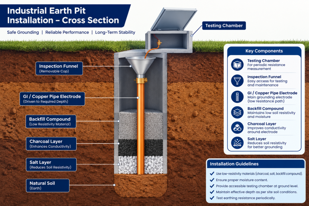
5. Critical Best Practices for Installation and Maintenance
- Eliminating Galvanic Corrosion: Never link disparate metals underground (such as copper wire directly bolted to a galvanized iron pipe). The resulting electrochemical reaction accelerates corrosion, destroying the earth path over time. Use high-grade bimetallic transition connectors.
- Equipotential Bonding Integrity: Ensure all metallic cable trays, structural steel columns, transformer neutrals, and motor chassis are securely tied back to the main earth busbar (MEB) to eliminate hazardous potential differentials.
- Periodic Testing Protocols: Execute annual maintenance schedules utilizing the Fall-of-Potential Method with a 3-point/4-point digital earth resistance tester to verify that resistance levels have not degraded due to soil shifting or chemical leaching.
Engineering Note on Target Resistance
While standard commercial installations generally mandate an earth resistance under 5 Ω, critical infrastructure such as data centers, telecommunication towers, power generation plants, and sensitive medical imaging suites frequently require values restricted to 1 Ω or lower.
Looking for Advanced Electrical Safety & Engineering Solutions?
Discover high-performance earthing components, distribution boards, and industrial infrastructure systems built to global engineering specifications.
Visit Relco ElectricalsAbout the Author:
Meghna Baid is a marketing professional with 7 years of experience, specializing in the electrical industry. She excels in brand building, strategic messaging, and high-impact campaigns, blending creativity with data-driven precision. With a sharp understanding of B2B and technical markets, she crafts compelling narratives that drive results and build strong industry connections.
Reach out to her at marketing@relcoelectrical.com
