Types of Transmission Lines

0
Understanding Power Transmission Lines: From Grid Architecture to Line Hardware
Comprehensive Technical Guide to Power Grid Transmission Lines | Relco Electricals

Types of Transmission Lines in Power Grids: The Complete Technical Guide

Published by Relco Electricals | Infrastructure & Power Distribution Insights

In modern power infrastructure, the primary objective of an electrical transmission grid is to transfer large blocks of electrical energy efficiently from central generation units—such as thermal power stations, hydroelectric dams, and solar/wind installations—to regional load centers and distribution substations. Because generating stations are frequently situated far from industrial hubs and densely populated metropolitan areas, power grids rely on high-voltage transmission lines engineered to minimize line losses and withstand harsh ambient conditions.

Selecting the optimal transmission line configuration involves complex trade-offs between electrical performance, insulation level, mechanical tension, thermal ratings, and total capital cost. This guide provides an in-depth breakdown of transmission line classifications, mathematical circuit models, current choices, and core line hardware.

Types of transmission lines
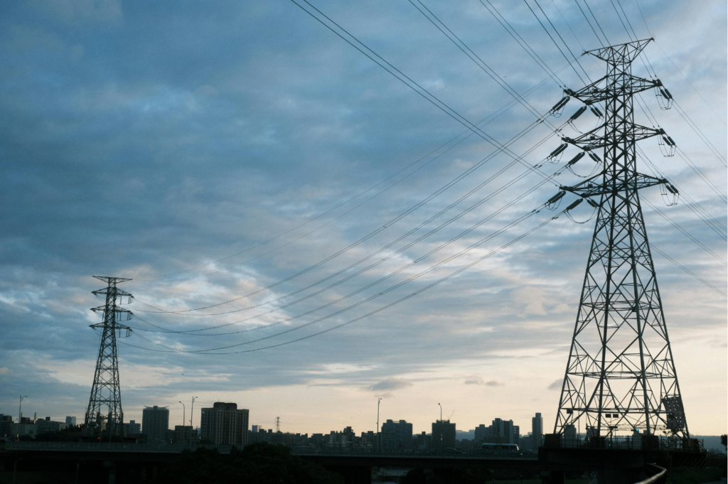
Figure 1: High-voltage overhead transmission corridor carrying bulk electrical energy across regional grid

1. Structural & Environmental Classification

Transmission networks are classified first by the medium in which conductors are routed and insulated from ground potential:

Overhead Transmission Lines

Bare conductors suspended elevated above ground level using structural steel lattice towers, tubular monopoles, or concrete poles. Ambient air acts as the main dielectric insulation medium.

  • Typical Operating Voltages: 66 kV, 132 kV, 220 kV, 400 kV, to 765 kV AC.
  • Key Advantage: Lowest capital expenditure per kilometer; straightforward visual inspection and phase maintenance.
  • Design Challenge: Vulnerable to lightning strikes, severe wind loads, ice accumulation, and right-of-way (RoW) acquisition limits.

Underground Transmission Cables

Fully insulated conductor assemblies installed inside sub-surface trenches, direct burial, or concrete duct banks. Insulation relies on XLPE (Cross-linked Polyethylene) or fluid-filled dielectric materials.

  • Typical Operating Voltages: 33 kV up to 220 kV (Special applications reach 400 kV).
  • Key Advantage: Immune to atmospheric weather disruptions; zero visual pollution; ideal for dense urban centers.
  • Design Challenge: 3 to 6 times higher initial cost; high charging current due to elevated cable capacitance; complex fault location procedures.

Submarine Transmission Cables

Heavily armored, water-sealed underwater cables designed for crossing sea channels, linking offshore wind turbines, or establishing cross-border marine grid interconnections.

  • Typical Systems: High-Voltage Direct Current (HVDC) light cables or multi-core XLPE AC cables.
  • Key Advantage: Enables bulk power transfers across large ocean bodies and remote islands.
  • Design Challenge: Requires specialized cable-laying vessels, ocean floor trenching, and anchor protection barriers.

2. Length-Based Electrical Parameter Classifications

In power system analysis, transmission lines are characterized by four distributed primary constants: Resistance (R), Inductance (L), Capacitance (C), and Shunt Conductance (G). Depending on physical route distance, these parameters determine whether line capacitance can be ignored or must be modeled as a distributed parameter wave propagation system.

Line Category Physical Length Nominal Voltage Capacitance & Modeling Method
Short Transmission Line < 80 km (< 50 miles) Up to 20 kV Negligible Capacitance. Charging current is small enough to ignore. Modeled purely as a series R-L circuit. Voltage regulation is straight-forward.
Medium Transmission Line 80 km to 250 km (50–150 miles) 20 kV to 100 kV Lumped Capacitance. Line capacitance is active and concentrated at specific nodes using equivalent Nominal-π (Pi) or Nominal-T circuit representations.
Long Transmission Line > 250 km (> 150 miles) > 100 kV (400 kV, 765 kV) Distributed Parameters. R, L, C, and G are spread continuously along every kilometer. Requires hyperbolic wave equations (rigorous ABCD matrix analysis) and reactive power compensation.
Overhead grid conductors navigating sub-transmission routes near urban load centers.
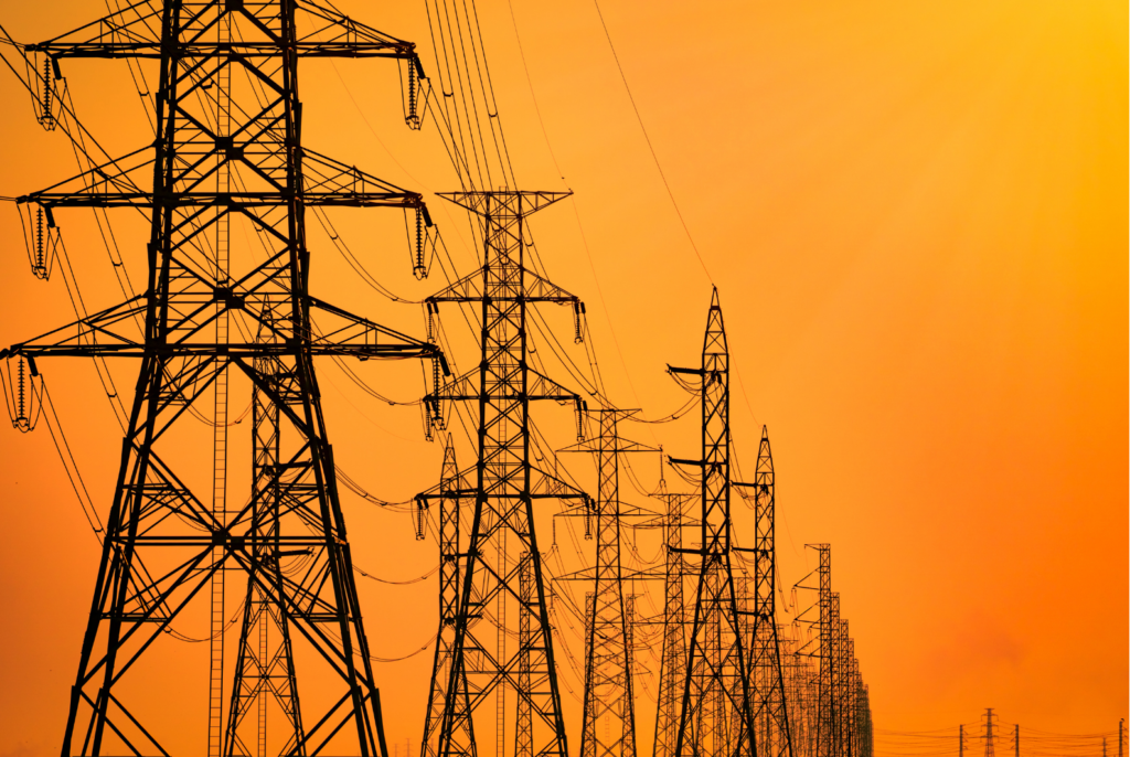
Figure 2: Overhead grid conductors navigating sub-transmission routes near urban load centers.

⚡ Interactive Tool: Transmission Line Classifier

Enter the route length of an electrical line to determine its parameter modeling requirement and mathematical behavior:

3. Transmission Current: HVAC vs. HVDC Systems

The choice between Alternating Current (AC) and Direct Current (DC) plays a pivotal role in long-distance bulk power transfer efficiency:

High-Voltage Alternating Current (HVAC)

HVAC is the foundational standard for electricity grid interconnection around the world. Because AC voltage levels can easily be transformed up or down using static power transformers, integrating regional generation sources with local municipal sub-transmission grids is extremely economical.

  • Optimal Operating Distance: Standard grid networks under 400–500 kilometers.
  • Key Advantages: Lower switching station equipment costs; straightforward tapping of intermediate power loads; flexible multi-terminal network expansion.
  • Limitations: Subject to reactive power voltage drops, skin effect (current density crowding on outer conductor surface), and Ferranti effect under light load conditions.

High-Voltage Direct Current (HVDC)

HVDC technology utilizes rectifier stations to convert AC power into DC, transmits bulk power over specialized two-pole transmission lines, and uses inverter stations to reconvert DC back to AC. Because DC current does not induce continuous capacitive charging, HVDC removes distance-related charging power limits.

  • Optimal Operating Distance: Point-to-point overhead routes over 500–600 km, or submarine cables exceeding 50 km.
  • Key Advantages: Zero capacitive reactance loss; no skin effect; allows asynchronous interconnections between power grids operating at different frequencies or un-synchronized phases.
  • Limitations: High capital cost for converter station transformers, thyristor/IGBT valves, and harmonic filter banks.

4. Essential Hardware Components & Overhead Line Fittings

An overhead high-voltage transmission line depends on precision-engineered mechanical hardware to maintain electrical insulation, absorb environmental vibration, and support structural conductor weight under wind and ice loads:

  • Conductor Materials (ACSR & AAAC): Modern lines predominantly use ACSR (Aluminum Conductor Steel Reinforced) or AAAC (All Aluminum Alloy Conductor) cables. The outer aluminum strands deliver high electrical conductivity, while the core high-tensile steel core (in ACSR) provides mechanical strength against sag.
  • High-Voltage Insulators: Disc, suspension, long-rod, and strain insulators manufactured from porcelain, toughened glass, or silicone polymer prevent leakage currents from passing from live conductors into grounded lattice tower bodies.
  • Vibration Dampers (Stockbridge Dampers): Tuned mass dampers mounted near conductor clamps absorb aeolian vibrations caused by laminar wind, preventing strand fatigue and mechanical wear.
  • Overhead Line Equipment (OLE) & Fittings: Heavy-duty strain clamps, suspension clamps, socket clevises, ball eyes, and cantilever assemblies maintain conductor geometry and ensure structural clearance over decades of continuous operation.

Partner with Relco Electricals for Reliable Grid Hardware

High-performance power transmission networks demand uncompromised hardware reliability. Relco Electricals manufactures a comprehensive range of Overhead Line Equipment (OLE), transmission line fittings, insulator strings, and custom hardware assemblies tested to rigorous international standards.

Explore Relco OLE Product Range

Frequently Asked Questions (FAQs)

Transmission lines are primarily classified by installation medium into Overhead Lines, Underground Cables, and Submarine Cables. By length and electrical behavior, power engineers divide them into Short (<80 km), Medium (80–250 km), and Long (>250 km) lines.
The Ferranti Effect occurs on medium and long transmission lines during no-load or light-load conditions. The continuous capacitive charging current flowing through the line's series inductance causes the voltage at the receiving end to rise significantly higher than the sending end voltage.
Overhead transmission lines are significantly cheaper to construct (roughly 15% to 30% of the cost of underground lines of equivalent voltage capacity). They use natural air for insulation, allow faster emergency repair times, and avoid thermal heat dissipation issues associated with underground trench burial.
ACSR (Aluminum Conductor Steel Reinforced) utilizes high-conductivity outer aluminum strands wrapped around a high-strength central steel core. AAAC (All Aluminum Alloy Conductor) is made entirely of an aluminum-magnesium-silicon alloy, offering superior corrosion resistance in coastal areas and lower weight.
HVDC is preferred for bulk point-to-point power transfer over long overhead distances (typically exceeding 500 km) or long underwater submarine cable crossings (exceeding 50 km), as it eliminates distance-related capacitive charging losses and allows un-synchronized AC grid connections.