
Engineering Flashover Prevention: The Hidden Science of Insulator Shed Design
Part 1: The Invisible Shield of High-Voltage Infrastructure
Across thousands of miles of overhead transmission lines, high-voltage substations, and local distribution networks, one component stands silently between operational grid reliability and catastrophic blackout: the high-voltage insulator. Whether fabricated from traditional glazed porcelain, toughened glass, or modern silicone rubber composites, these structural components share a distinctive visual hallmark—a series of stacked, umbrella-like ridges, technically known as sheds, petticoats, or skirting.
To the untrained observer, these ridges might appear to be purely decorative features or structural reinforcements designed to support heavy aluminum and copper conductors. However, in high-voltage electrical engineering, shed geometry represents a masterclass in physics and material science. It directly counteracts one of the most persistent operational threats facing modern power systems: atmospheric surface tracking and environmental flashovers.
Understanding the Physics of High-Voltage Leakage
Overhead power lines carry immense electrical potentials, frequently ranging from 11,000 Volts (11 kV) in localized distribution circuits to over 765,000 Volts (765 kV) in extra-high-voltage (EHV) long-distance transmission corridors. High voltage naturally seeks the path of least resistance to the ground structure (such as steel lattice towers, wooden poles, or substation grounded frames).
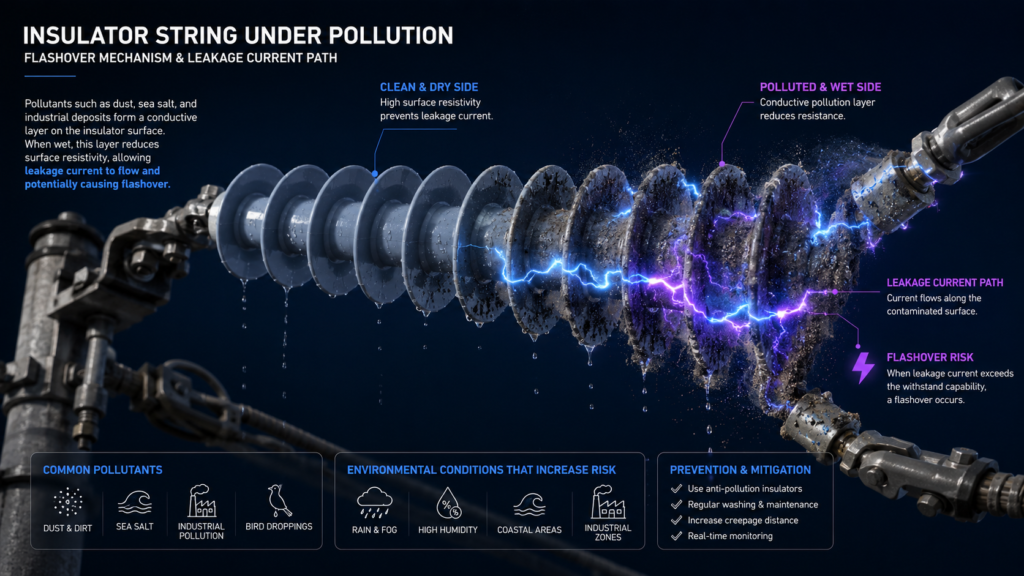
Under completely dry, pristine laboratory conditions, dry ambient air and the clean solid surface of an insulator provide immense dielectric strength. However, real-world utility networks operate under continuous environmental stress. Airborne contaminants constantly settle onto exposed equipment surfaces, creating a vulnerability that engineers must design around.
Part 2: The Geometric Science of Insulator Sheds
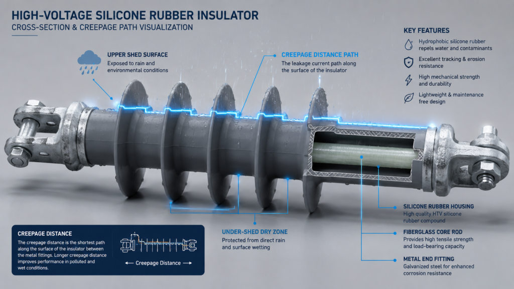
If high-voltage insulators were designed as smooth, uniform cylinders, utility companies would face an impossible dilemma. To prevent surface tracking on a smooth rod under heavy rainfall, an insulator operating at 220 kV would need to be over 15 to 20 feet tall! This would drastically increase tower height, mechanical loads, structural steel costs, and physical footprint. The invention of umbrella shed geometry solves this challenge entirely through physics.
💡 Engineering Insight: Umbrella sheds allow engineers to increase the actual surface distance electrical current must travel (Creepage Distance) by 200% to 400% without increasing the physical height or weight of the insulator!
Part 3: Material Evolution & International Standards
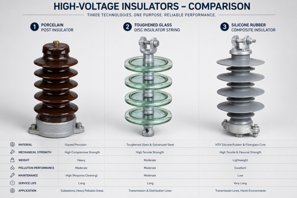
While the mechanical shape of insulator sheds provides geometric protection, material choice dictates long-term durability, hydrophobic properties, and maintenance cycles. Over the past century, material technology has undergone three major evolutionary shifts:
Glazed porcelain has been the industry standard for over a century. It offers unmatched mechanical rigidity for substation transformer bushings and heavy line termination points, with operational lifespans exceeding 50 years.
Glass disc strings are widely used on long-distance transmission lines. When an internal fault occurs, toughened glass shatters into harmless fragments without losing mechanical tensile strength, making helicopter/drone inspections instantaneous.
Composite insulators feature a fiberglass core enclosed in a molded silicone rubber housing. Silicone transfers hydrophobic oils to surface dirt, causing water to bead up into isolated drops rather than forming conductive sheets.
Grid Compliance: Calculating Creepage Ratios (IEC 60815)
Substation and transmission engineers do not select insulator profiles arbitrarily. Global infrastructure planning strictly adheres to international standards like IEC 60815 (Selection and dimensioning of high-voltage insulators intended for use in polluted conditions). Required creepage distances are mapped directly to localized Pollution Severity Levels (SPS):
- Class I (Very Light Pollution): Rural inland areas away from main roads (20 mm/kV of system voltage).
- Class II (Medium Pollution): Agricultural zones with frequent tilling or moderate industrial exposure (25 mm/kV).
- Class III (Heavy Pollution): High-density industrial zones or areas near major highways (31 mm/kV).
- Class IV (Very Heavy Pollution): Coastal regions exposed to sea spray, salt flats, or heavy chemical plants (38+ mm/kV).
Conclusion: Engineering Grid Reliability from the Ground Up
Modern electrical grids are incredibly complex networks incorporating smart automation, real-time telemetry, and advanced digital protection systems. Yet, all of that cutting-edge technology relies on fundamental physical principles. The simple, umbrella-shaped ridges on everyday outdoor insulators are silent engineering marvels—utilizing surface geometry, material hydrophobicity, and aerodynamics to prevent flashovers, safeguard multi-million-dollar transformers, and keep power flowing reliably to cities around the world.
About the Author:
Meghna Baid is a marketing professional with 7 years of experience, specializing in the electrical industry. She excels in brand building, strategic messaging, and high-impact campaigns, blending creativity with data-driven precision. With a sharp understanding of B2B and technical markets, she crafts compelling narratives that drive results and build strong industry connections.
Reach out to her at marketing@relcoelectrical.com